Blower Turbine - Free Energy
My name is Pranab Jyoti Ghosh and I am an Indian physics graduate and a person having lot of innovative ideas. From my college days, my hobby was to do personal research on alternative energy and a new kind of source of power that is very low grade heat including atmospheric heat. At present, I am in service but I want to consider myself as an inventor/innovator. And for a long time, I have been studying physical phenomenons from which a new technology can built that can harness low grade heat that is unusable with present day technologies and considered as waste, can be used to generate useful power/electricity. In this document, I want to present such an idea (though the basic parts are already built and tested) that can harness low grade heat (including atmospheric heat) and convert that into useful power/electricity.
The Technology :
The technology is about a new kind of machine capable of extracting atmospheric heat and converting that into useful power/electricity. This machine would be a combination of special kind of wind turbine that has been known as “concentrated wind turbine” in combination with a blower. The shape of the power generating section i.e. the wind turbine would cylindrical from outside and inside it would be fitted the blades that will rotate and the axis of machine would be connected to an alternator which would generate electricity and/or can supply necessary power to a machine for doing work. As it has already been said that power generation unit will be cylindrically shaped i.e. the entry of machine has circular cross-section. The blower too will have circular cross-section and that diameter would be the same or higher than that of the inlet of turbine. The blower will create the necessary flow of air that will rotate the power generating unit and will generate power. The output from machine would be a few times than the input to the blower. Some little other accessories are needed to ensure that all the flow coming from the blower would enter the power generating unit. One big advantage of the machine is that it can be switched on and off easily.
The basic advantage of the machine is that it doesn’t need any kind of fuel or source of heat other than the ambient heat surrounding us. Unlike the solar power, that is useless during night and cloudy days and wind power that is totally dependent on natural wind; this machine can supply power as per need almost any kind of day and any time during a day. It can also be used anywhere in the world and in any kind of environment. And against the power generation, it doesn’t create any kind of polluting gas and/or residue and no kind of radiation. And for tropical part of the world and during summer, this can be a source of cooling without any extra cost.
Basic structure of the machine :
Proof :
The very basic parts those are needed to make the machine is a blower and the power generating unit that is the turbine. Blowers of necessary power and structure are already available in market and it can’t be big problem to find the blower. The most important part is the power generating part that is the concentrated wind turbine. Various kinds of such turbines are now available in market and is being successfully used around the world. One such machine is INVELOX created by SheerWind Inc. This machine can generate 5-6 times power in comparison to conventional wind turbine of similar size. It’s tested and now in use in many projects and power generation units around the world.
The special kind of concentrated wind turbine that is needed for this machine is already built and tested. On wind tunnel testing, the machine has been found to be able to generate 3 kW output at 8 m/s velocity and the machine has 1 meter diameter at the inlet. While a blower of 1 meter diameter and 500 W input can generate 8 m/s wind. In short, if the all the flow from the blower can enter the machine and it will generate 6 times more output than the input. The efficiency mentioned i.e. 50% is a modest efficiency and models of blower with higher efficiency is now available in market. And with higher efficiency, the output from the power generating unit will increase according and there are many ways by which the power output can be increased by keeping the input the same.
But, the unique point of this machine is use of internal enthalpy of air to generate power/electricity and no such machine is now available in market anywhere in the world. The power generating section is now being used as wind turbine and the inventor of the machine hasn’t claimed it as a machine capable of extracting atmospheric heat and converting that into useful power/electricity. But, by using a blower to generate the airflow, this unique combination of blower and the power generating unit is now capable of extracting atmospheric heat and converting that into electricity. Necessary theoretical analysis and mathematical calculations can also be presented if necessary..
How To Make It :
As both the blower and the power generating unit will have the same circular cross-section, what is needed is to make a tunnel shaped pathway from the blower to power generating unit that will be attached to both by flanges. Both the blower and the machine is now market available and they are most important part. The total cost of making small scale 3 kW unit wouldn’t exceed US$ 2500 even at this experimental stage. And with bigger models, the cost would decrease simultaneously and on large scale, the capital cost of a power plant based on this technology would be much less in comparison to a thermal power plant now functioning.
Detailed Description :
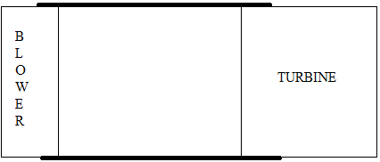
Shown above is a simplified cross-sectional view of the whole machine and that too isn’t dimension wise but rather representative only. It’s like a tunnel where the blower will be fitted at one end and the turbine at the other end. The main purpose of the tunnel is to channelize all flow created by the blower to the turbine and no part of the flow to be diverted outside the turbine. The blower will create the flow and that flow will rotate the turbine. The type of blower needed for the set can be found in market. The main parameter of the blower is that its diameter should be equal or greater than the diameter of the turbine, but shouldn’t be less in any case. And the efficiency of the blower should be 50% minimum and as high as possible.
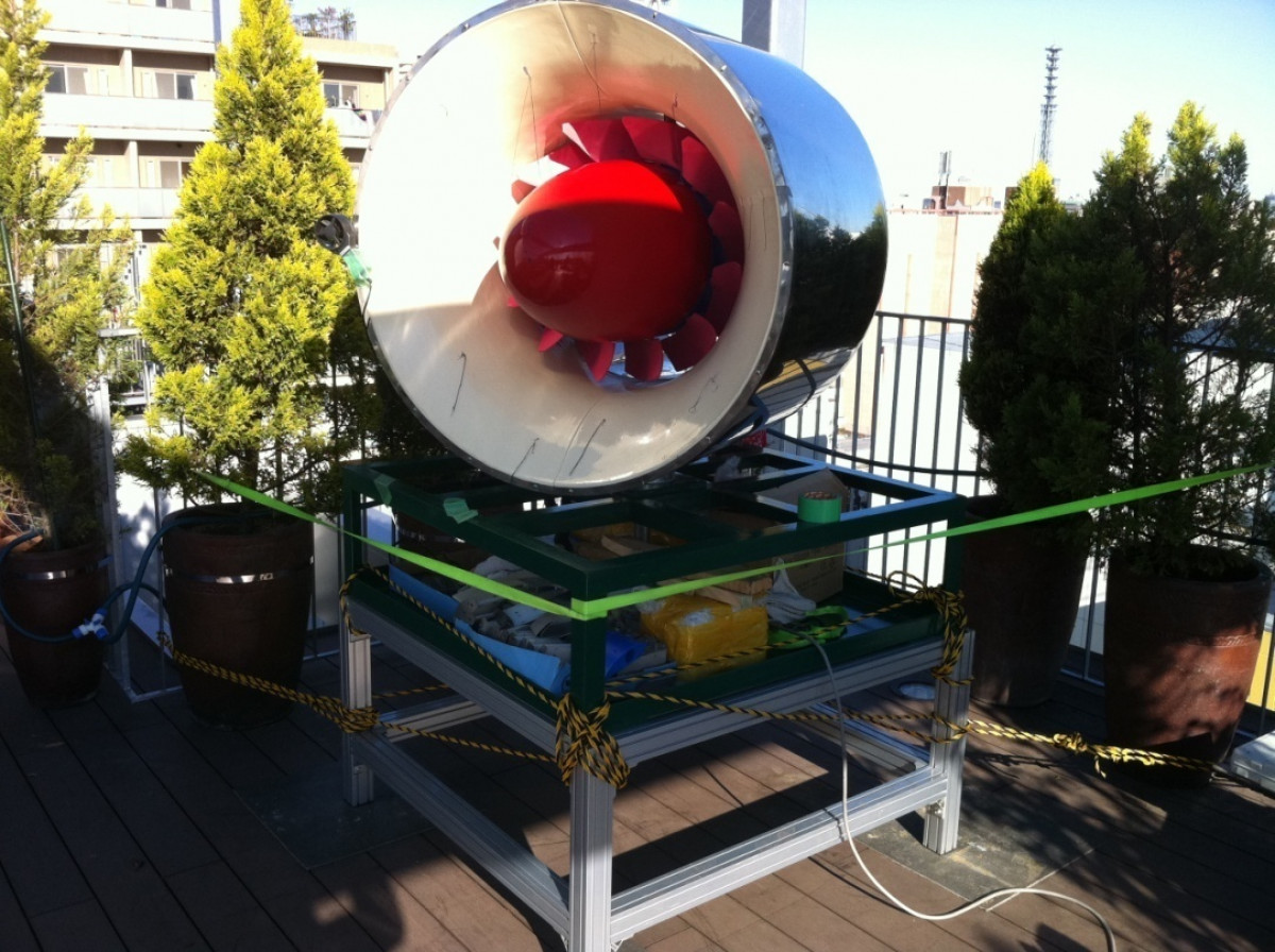
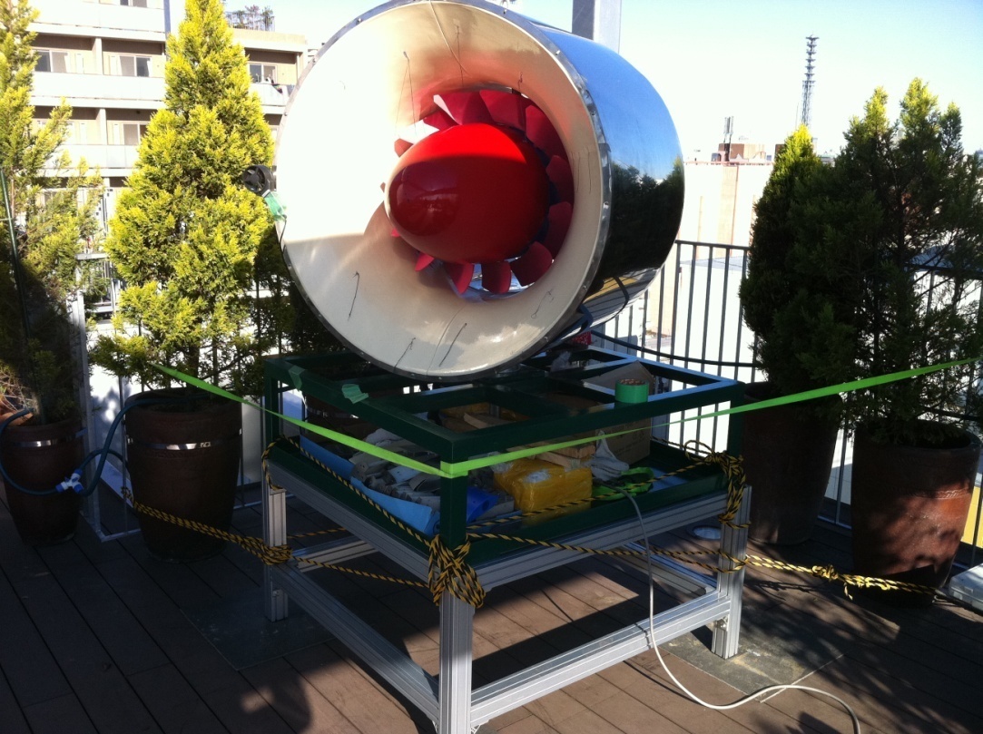
The main part that will convert the enthalpy of the incoming flow into useful power/electricity is the turbine and for the prototype version, a new kind of concentrated wind turbine invented by Japanese inventor Tsuneo Fukui can be used. The details of the turbine, that is the most important part of the whole set has been given below.
It’s called a ring type concentrated wind turbine. The main advantage of the turbine for generating so much electricity with such a smaller size is the entry point of the turbine. The airflow passes through a rim type space before hitting the blades of the turbine. The entry area is 0.78 sq meter, but the exit area of the flow just before hitting the turbine blades is 0.15 square meter. So, the velocity of the flow will increase accordingly by obeying the basic laws of subsonic compressible flow through a convergent nozzle. When a subsonic flow enters a convergent nozzle, its velocity increases as it approaches the throat that is the narrowest part of the nozzle and its velocity reached the peak at the throat. This extra velocity comes at the expense of internal enthalpy of the fluid (in this case air) and both its pressure and temperature falls. This fact has been proven theoretically and in reality for many times. And this invention uses this phenomenon to generate much more power that has been consumed by the blower to create the flow.
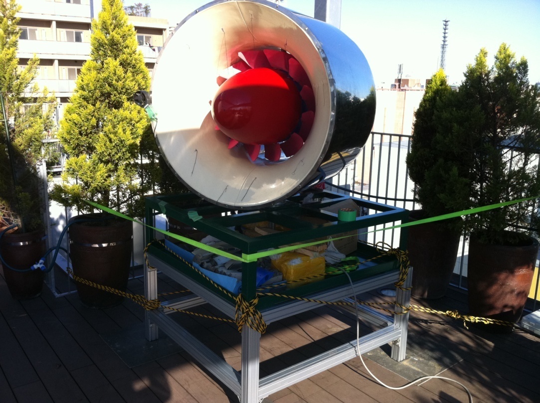
Given above is a photo of the finished turbine prototype with 12 blades inside.
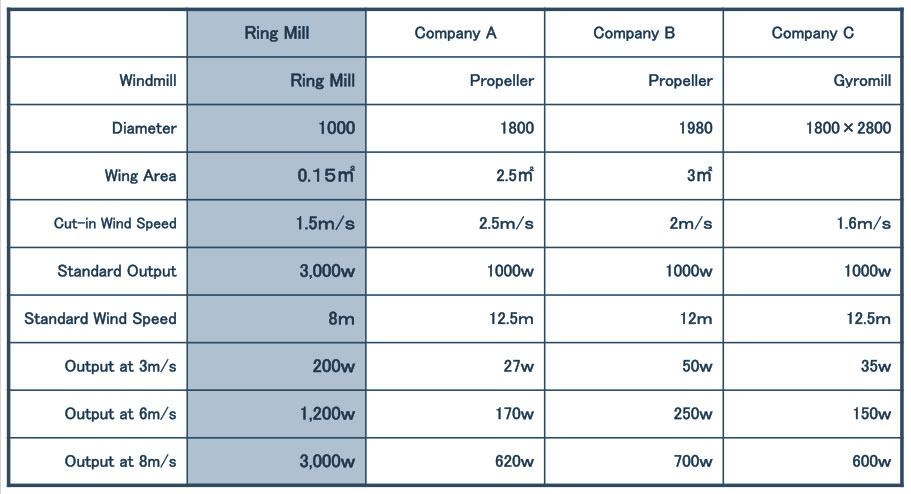
And given above is the wind tunnel test report of this turbine and its comparison with other type of conventional wind turbines available in market. And this turbine is just an example; there are other similar kinds of examples available. As for example, INVELOX is another concentrated wind turbine that generates 5-6 times power in comparison to a conventional wind turbine or similar size. And, on many type of experimental set ups, it has been found that Venturi effect can increase power output of wind turbines.
Poins To Be Noted :
There are simpler models available than the one shown above which can be made and installed easily. The example above has been chosen because it was already built and tested and therefore similar output can be expected.
Man Point :
So far, all the experiments has been conducted for wind turbines and it has been found that by using venturi effect, power output from wind turbines can be increased a few times. But, so far, none have noticed that if the flow has been created by machine i.e. by a blower or anything else, even in that case, the power/electricity output from the turbines can be a few times more than the input energy of the blower. As for example, in the case of the turbine mentioned above, the power output at 8 m/s velocity is 3 kW. While a blower of 1 meter diameter and 50% efficiency and generate 8 m/s airflow with just 500 W input. And 50% efficiency is a very modest efficiency and there are blowers available in market those have higher efficiency. The main point of this extra power is the conversion of internal enthalpy at the entry point of the turbine where the velocity of the flow has been increased at the expense of its own enthalpy and that increased velocity has been converted to power by the blades of the turbine.
A Few Points Regarding Bernoulli's Theorem And Other Factors :
Bernoulli’s theorem, at least in the equation as we know it, says that fall in pressure is proportional to the increase in velocity i.e. dynamic pressure. From the available equation of Bernoulli’s theorem, it can be calculated that the fall in static pressure is exactly equal to the rise in dynamic pressure and that means no change in gross pressure of the fluid. But, there are glitches in that equation. Bernoulli’s equation is applicable to both compressible (gaseous) and non-compressible (liquid) fluids and while calculating based on Bernoulli’s equation, the fluid has been considered to be non-compressible i.e. there is no change of volume despite the change in pressure. in short, the change will follow ideal gas equations just like other isothermal processes.
But, that’s not the case for a gaseous fluid flowing through a convergent nozzle at subsonic velocity. The change is adiabatic here and that means the relation between the fall in pressure isn’t directly proportional to the fall in temperature and at the same time the rise the dynamic pressure. to do that, we have to start from the viewpoint of first law of thermodynamics and by applying laws of adiabatic change.
In case of adiabatic change, we know that internal enthalpy has been converted into velocity and the equation is:
CV.ΔT = ½ Mv2
M is molecular mass of the gas in gm
CV is specific heat of one gm-mole of gas
And v is the final velocity in case the gas starts from zero velocity.
That means, if we know the initial and final velocity and also the density/molecular mass of the gas, then the fall in temperature can be easily calculated. And the rise in dynamic pressure can be also be calculated by this method.
But, the fall in static pressure can be calculated from the fall in temperature by using the adiabatic change formula only and if we use the formula to calculate the fall in static pressure and the rise in dynamic pressure, almost in call cases staring from normal temperature from our surroundings, we can see that the rise in dynamic pressure will be higher than the fall in static pressure. the fall in static pressure is also dependent on the initial temperature of the gas. The higher the initial temperature, less will be the fall in static pressure while the rise in dynamic pressure will remain the same.
Let’s start with one practical example where detailed calculations are avoided to get rid of unnecessary complexity. If the initial temperature is 20°C and the static pressure is 1 barA and the nozzle will increase the velocity from 1 m/s to 300 m/s and the gas used is pure dry Nitrogen, then we can see that the fall in temperature is around 60°C. The fall in pressure calculated is found to be just 0.063 barA while the rise in dynamic pressure is 0.56 barA. If needed, necessary calculations can be shown.
And there is another factor that’s available almost everywhere in our surrounding atmosphere and that’s humidity. The calculation shown above is based on the fact that the gas used is pure, dry Nitrogen. If humidity is added to it, the fall in temperature would be much less because as the temperature falls, the humidity will condense and the latent heat of vaporisation of that vapour will be released into the air. That will again raise the temperature and that means that the fall in static pressure will be much less. As for example, if sufficient humidity is added to the previous case, the fall in temperature will fall to around 10°C and that means much lesser fall in pressure while the rise in dynamic pressure will be same.
About Me:
My name is Pranab Jyoti Ghosh and I am an Indian physics graduate and a person having lot of innovative ideas. From my college days, my hobby was to do personal research on alternative energy and a new kind of source of power that is very low grade heat including atmospheric heat. At present, I am in service but I want to consider myself as an inventor/innovator. And for a long time, I have been studying physical phenomenons from which a new technology can built that can harness low grade heat that is unusable with present day technologies and considered as waste, can be used to generate useful power/electricity. In this document, I want to present such an idea (though the basic parts are already built and tested) that can harness low grade heat (including atmospheric heat) and convert that into useful power/electricity.
Powered by Froala Editor
