- Technology
- Spirituality
- Science
- Medicine
- Alchemy
- Culture
- Education
- Environment
- Agriculture
- Industry
- Social
- History
- Amazing people
The Magnetic Engine
Written by Fulmina Institut
Presented by Fulmina Institut And PROOF GLOBAL CORPORATION By David Brooks Nixon, Executive Chair Dr. Robert Abraham Hallowitz, MD, Executive Director VENTURI LLC Richard Keith Wood, Chief Executive Officer Denis L. Palmer, Inventor, Chief Engineer.
July 2017
A Free Energy Technology
Preamble
We are presenting here one example of Free Energy Technology that incorporates a series of very practical features and represents a significant jump in the efficiency of most electricity generating devices.
The device can solve a number of situations where energy is the costliest part of the problem. Water desalination, growing vegetables, automobiles, ships and airplanes power plants, smelters. The list of necessary applications is growing. A United States Patent No. US 2012/0326541 A1, has been granted.
This report has been produced by the scientists associated with PROOF GLOBAL CORP.; it was submitted for analysis to the Academy of the Fulmina Human Resources Foundation.
Abstract
This invention presents a highly efficient electric motor which can be embodied in several configurations, including a standard motor, a hub motor, a linear motor, or other motor configuration. As a regenerative device, the motor may also act as a part-time or full-time electrical generator. There is provided a motor composed of a stator and a rotor. The stator has an array of coils arranged therein. The rotor has an array of magnets arranged therein. Each of the coils includes a first winding of wire wrapped around a core, and the wire has a non-circular cross-section. The wire can be a flattened wire.
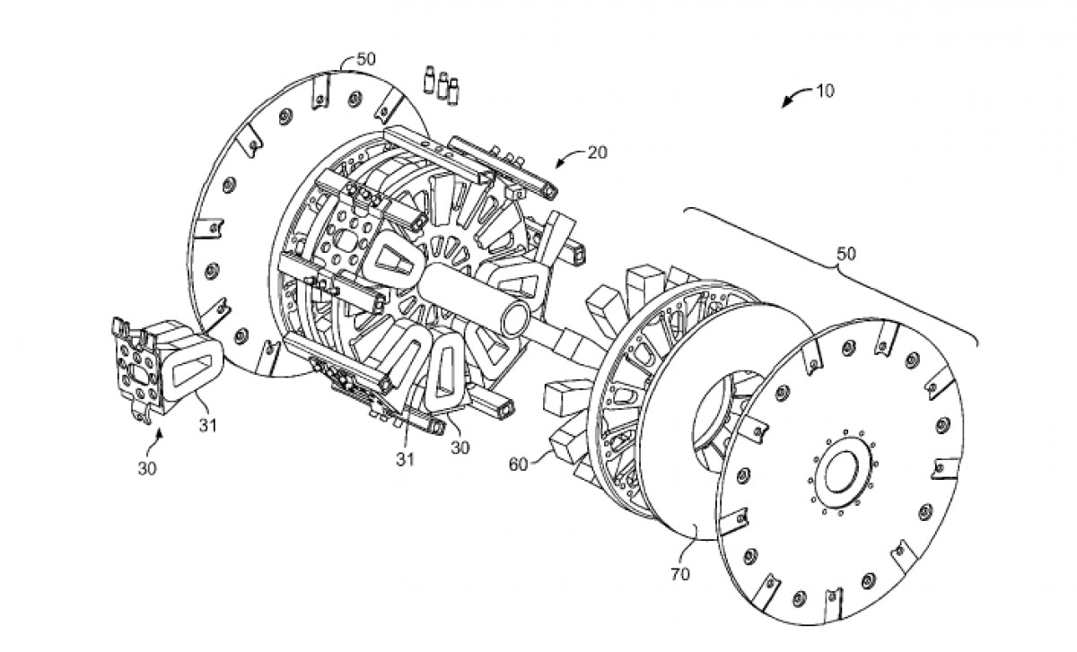
Graphics Extracted from Patent Application

Introduction
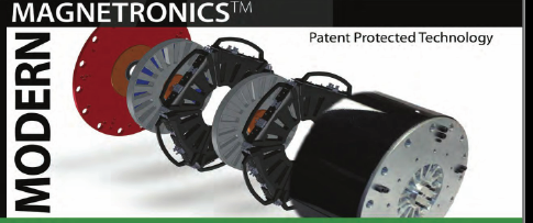
The MagnetronicTM patent suite, brings the design of the electric motors generators into the 21st century. Magnetronic is the only modular generator design enabling radial arrangement of coils and magnets which, while rotated, creates more clean inductive electricity — and the best news is, they are 150% greater in efficiency.
The technology advancement, tested and proven, is both modular and scalable, and fully analogous to the jump from the telegraph to cellular phones. Generators commonly used in the industry cannot be repaired in the field. They are either discarded or must be taken down with expensive equipment in fair weather and returned to the factory for a complete breakdown and rebuild resulting in high repair costs and low real efficiency, and experience high operating costs. In complete contrast, the Magnetronic Coil Windings require simple manufacturing processes, modular, free of iron, easy to scale, and are easily replaceable while the motor is in operation.
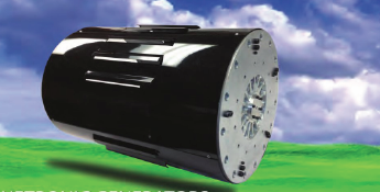
Several technological advantages are present in the Magnetronics motors. The motor provides high efficiency and ultra-low operating costs, the lowest cost per horsepower of any motor to date, and it is the least expensive and easiest to service. The applications for our motor are endless from powerful semi-truck type systems to electronic bicycles, not to mention the vast arrays of electrical generators.
Magnetronic motor generators are multi-phase electric motor; they comprise a stator designed with a plurality of wire coils surrounding by a non-magnetizable core; a rotor with permanent magnets embedded therein, the rotor being disposed adjacent to the stator, the rotor being mounted on a rotatable drive shaft; a power source; a position sensor operably connected to the rotor; and a control circuit operably connected to the power source, the position sensor, and the wire coils, for controlling distribution of electrical energy to the wire coils. In this motor the control mechanism transfers electrical charge from a first coil to a second coil.
The following response applies to all motor generators. Our motor generators have the unique ability to be built in multiple sizes from small dentist motorized utensils to massive multi-horsepower motor generators. Dimension can range from small “skinny” straw-like configurations to short large-diameters. Due to this flexible arrange of elements in a particular array, the Motor Generators can be built in all dimensions and for multiple operations including variable speeds, constant speed, constant torque, as well as specific positioning.
All element arrangement arrays represent our technology. The capabilities are literally limitless with applications requiring motion or response motion (motor generator).
As energy costs continue to rise and supplies dwindle, there is a substantial need for more efficient use of energy, particularly for electric motors. Electric motors do power many devices on this planet, and thus improvements in power output from motors for a given input energy would mean significant savings in energy costs. One usage in particular that would benefit from an improved electric motor is electric vehicles. Although electric vehicles have been around for over one hundred years, they have only recently begun to become widely used. Improvements in electric motor power output would help electric cars become even more practical and accepted in the marketplace.
Motors having electromagnetic coils without metal cores have been used before, for example, in ‘pancake’ type motors generally used in low power applications. However, non-magnetizable core materials such as plastics have not been used for high power motors. What is needed in the art are new ideas for building and controlling electric motors to produce a more energy-efficient electric motor. In one embodiment the of the Magnetronic motor generator, is a multi-phase electric motor, comprising a stator comprising a plurality of wire coils surrounding a non-magnetizable core; a rotor with permanent magnets embedded therein, the rotor being disposed adjacent to the stator, the rotor being mounted on a rotatable drive shaft; a power source; a position sensor operably connected to the rotor; and a control circuit operably connected to the power source, the position sensor, and the wire coils, for controlling distribution of electrical energy to the wire coils; wherein the control mechanism transfers electrical charge from a first coil to a second coil.
In another embodiment the motor generator is a method of operating an electric motor, comprising the steps of providing an electric motor comprising: a stator comprising a plurality of wire coils surrounding a non-magnetizable core; a rotor rotatably mounted adjacent the stator; a plurality of permanent magnets mounted to the rotor; a power source; a position sensor operably connected to the rotor; and a control circuit operably connected to the power source, the position sensor, and the wire coils, for controlling distribution of electrical energy to the wire coils.
The invention of this embodiment further comprises electrically energizing a first coil with the power source; electrically connecting the first coil to a second coil, thereby transferring electrical energy from the first coil to the second coil under direction of the controller; and disconnecting the first coil from the power source.
In yet another embodiment of the motor generator is a multi-phase electric motor, comprising: a stator comprising a plurality of wire coils surrounding a non-magnetizable core, wherein the non-magnetizable core comprises a plastic tube; a rotor with permanent magnets embedded therein, the rotor being disposed adjacent to the stator, the rotor being mounted on a rotatable drive shaft; a power source; a position sensor operably connected to the rotor through the drive shaft; and a control circuit operably connected to the power source, the position sensor, and the wire coils, for controlling distribution of electrical energy to the wire coils; wherein the control mechanism transfers electrical charge from a first, discharging coil to a second, charging coil; wherein the rotor comprises a disk having a pair of opposite faces with a circumferential edge there between; wherein the rotor further comprises a steel ring attached to a face near the circumferential edge; wherein the permanent magnets comprise a piece of steel sandwiched between two rare earth magnet pieces, such that at least one rare earth magnet is adjacent to the stator.
Further areas of applicability of the invention will become apparent from the detailed description provided hereinafter. It should be understood that the detailed description and specific examples, while indicating the preferred embodiment of the invention, are intended for purposes of illustration only and are not intended to limit the scope of the motor generator.
Claims
A multi-phase electric motor, comprising: a stator comprising a plurality of wire coils each surrounding a non-magnetizable core; at least one rotor with permanent magnets embedded therein, the rotor being disposed adjacent to the stator, the rotor being mounted on a rotatable drive shaft; a power source; a position sensor operably connected to the rotor; and a control circuit operably connected to the power source, the position sensor, and the wire coils, for controlling distribution of electrical energy to the wire coils; wherein the control circuit transfers electrical charge from a first coil to a second coil.
The multi-phase electric motor of claim 1 wherein the first coil is a discharging coil.
The multi-phase electric motor of claim 2 wherein the second coil is a charging coil.
The multi-phase electric motor of claim 1, wherein the rotor comprises a disk having a pair of opposite faces with a circumferential edge there between, wherein the disk is made of a non-magnetizable material.
The multi-phase electric motor of claim 1, wherein the rotor comprises a steel ring attached to a face near the circumferential edge.
The multi-phase electric motor of claim 1, wherein the permanent magnets comprise a piece of steel sandwiched between two rare earth magnet pieces, such that at least one rare earth magnet is adjacent to the stator.
The multi-phase electric motor of claim 1, wherein the position sensor comprises at least one of: cam-driven spring contacts, brushes, a magnetic distributor, and a photoelectric distributor.
The multi-phase electric motor of claim 1, wherein the position sensor is operably connected to the rotor through the drive shaft.
The multi-phase electric motor of claim 1, wherein each wire coil comprises wire windings that are in a plane that is parallel to a plane of rotation of the rotor.
The multi-phase electric motor of claim 1, wherein the non-magnetizable core comprises at least one of: a plastic tube, a rod, and an air core.
The multi-phase electric motor of claim 1, further comprising: a hollow tubular spacer projecting from a face of the rotor, the spacer being mounted at the rotational center of the rotor coaxial with the drive shaft, the spacer surrounding the drive shaft, such that the spacer maintains a fixed distance between the rotor and a second, adjacent rotor.
The multi-phase electric motor of claim 1, further comprising: a frame structure for supporting the stator relative to the rotor comprising a plurality of longitudinal strips fixedly attached to a pair of end plates; wherein the drive shaft is supported by the end plates; wherein the wire coils of the stator are removably attached to the longitudinal strips.
The multi-phase electric motor of claim 1, wherein the stator comprises six coils and the rotor comprises eight permanent magnets.
A multi-phase electric motor, comprising: a stator comprising a plurality of wire coils each surrounding a non-magnetizable core, wherein the non-magnetizable core comprises a plastic tube; a rotor with permanent magnets embedded therein, the rotor being disposed adjacent to the stator, the rotor being mounted on a rotatable drive shaft; a power source; a position sensor operably connected to the rotor through the drive shaft; and a control circuit operably connected to the power source, the position sensor, and the wire coils, for controlling distribution of electrical energy to the wire coils; wherein the control circuit transfers electrical charge from a first, discharging coil to a second, charging coil; wherein the rotor comprises a disk having a pair of opposite faces with a circumferential edge there between; wherein the rotor further comprises a steel ring attached to a face near the circumferential edge; wherein the permanent magnets comprise a piece of steel sandwiched between two rare earth magnet pieces, such that at least one rare earth magnet is adjacent to the stator.
The multi-phase electric motor of claim 14 wherein the position sensor comprises at least one of: cam-driven spring contacts, brushes, and a photoelectric distributor.
The multi-phase electric motor of claim 14, wherein the disk is made of at least one of: aluminum and phenolic resin.
The multi-phase electric motor of claim 15, wherein each wire coil comprises wire windings that are in a plane that is parallel to a plane of rotation of the rotor.
The multi-phase electric motor of claim 14, wherein the stator comprises six coils and the rotor comprises eight permanent magnets.
A modular, multi-phase electric motor, comprising: a stator comprising a plurality of wire coils each surrounding a non-magnetizable core; at least one rotor with permanent magnets embedded therein, the rotor being disposed adjacent to the stator, the rotor being mounted on a rotatable drive shaft; a frame structure for supporting the stator relative to the rotor, the frame structure comprising a plurality of longitudinal strips extending between a pair of end plates; a power source; a position sensor operably connected to the rotor; and a control circuit operably connected to the power source, the position sensor, and the wire coils, for controlling distribution of electrical energy to the wire coils; wherein the drive shaft is supported by the end plates; wherein the wire coils of the stator are removably attached.
Science of Magnetronic — Operation and Principles
Magnetronic systems use multiple algorithmic rules to achieve remarkable results in electricity generation and motor drive propulsion. Magnetic fields flow to current limiting coils, similar to industry standards of Hall effect Transistors. The magnetic field of the permanent magnets are used to limit current through coil operations. Other motor generators use counter EMF to limit current causing different effects.
Magnetic fields addition for every magnet in a magnetic circuit. The magnetic fields of all magnets in the array add to the power of each magnet in the system, increasing the available effective force.
Magnetic fields containment. The magnetic fields are contained and focused to limit losses and increase forces availability. The resonance recapture of energy is not consumed by using high speed electronics to capture the returning (collapsing field energy) without heat conversion as is found in standard motor generators, which causes significant loss of energy. These basic rules are fundamentally combined to make the Magnetronic motors work with the several advantages including less heat, less required startup current, less resistance, less operational current — draw, and more power output.
A strong magnetic field is also used to limit current through a coil. Set up properly, this rule reduces the current and at the same time increases forces, derived from the current being pushed through a coil. By the configuration and location of the coil in relation to the magnets, the force is maximized and the current is reduced. The result is increased output force when compared to power consumed.
By being completed and by adding more magnets to the circuit, each adds to the force of every magnet and the relationship of these magnets to each other limiting the leakage between the polls maintains the forces in correct alignment also maximizing the output. The precise configuration in perfect balance eliminates the losses associated with other technologies.
Copyright Fulmina Foundation
Powered by Froala Editor